 Contact
Home
Chapters
Contact
Home
Chapters
TB10D Upgrade
Lets have some fun ...
Over the last decade or so the Mini-Amp revolution has been heating up as these amplifiers become more and more capable in surprisingly small cabinets and at prices that are hard to ignore. This is mostly made possible by advances in Class-D amplification giving us the high quality "amp on a chip" designs that can and do deliver astonishing levels of power with excellent sound quality.
Unlike it's predecessor technologies, Class-D does not use brute strength to deliver it's output. Instead it uses a modulation technology known as Pulse Width Modulation or PWM, for short. In this scheme an audio signal is used to Modulate the ratio of on-time to off-time in a high frequency chain of square waves. After that, all you need to do to get the amplified audio back is filter out the square waves. It's simple and when done right it is very effective and surprisingly efficient.
One chip in particular, the TPA3255, has reached such a level of popularity that it's almost everywhere in the mini-amp market. It's a great chip with surprising capabilities at a very reasonable price, so it makes sense that a large number of products have popped up using it.
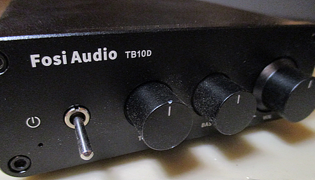
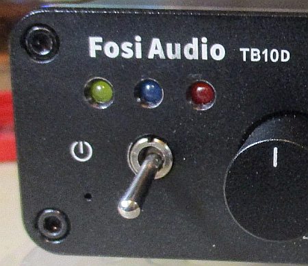
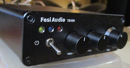
One product, the Fosi Audio TB10D has all the right stuff, but a bit of a history as well. Originally panned by subjective reviewers, it was upgraded then loved. It has all the trappings, a discrete power switch, tone controls and, of course, that beautiful TPA3255 chip. However, deep examination reveals there are still a few issues with this design. It can be better.
So, lets fix the issues, then (optionally) add Clipping and Protection indicators to complete the upgrade...
The following is advanced level DIY modification. You will need to be skilled
with soldering, hand tools and test equipment to successfully complete
these tasks.
On when off Home Top Chapters
There have been several versions of the TB10D circuit board. These are marked on the top side near the output coils. For versions earlier than 2.1 the amplifier could actually remain on and active even when the power switch was in the off position. This, obviously is not a good thing.The TPA3255 has a ~RESET signal on pin 18. To shut the amplifier down into its low power standby mode, this pin needs to be grounded. Turning it back on requires 3.3 volts to be applied to this pin. However, if the pin is left to float, it can drift up allowing the amplifier to turn itself on.
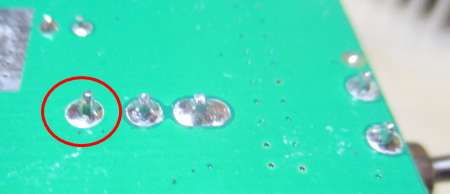
In the TB10D this is controlled by the power switch. To check if the ~RESET is left to float, look at the bottom of the board, right under the power switch. In the image at the right, the "off" pin is circled in red. A multi-meter should show 0 ohms or beep for continuity when touching this pin and ground.
On versions before 2.1 this pin was floating. The correction is to gently scratch away a little bit of the green solder resist to expose a tiny bit of copper right next to this pin and then deliberately solder-bridge it to ground. There is very little current here, so keep the bridge as small as you can.
In version 2.1 they did the solder bridge for us. In the 2.2 and later versions the board has been corrected to fix this problem.
Logic Supply Voltage Home Top Chapters
This applies to all versions of the TB10D circuit board to date (ver 2.2).The TPA3255 uses 3.3 volt signals for it's internal logic. The ~RESET pin (18) is specified for an absolute maximum of 4.7 volts with its logic 1 state at 1.8 volts. To be safe and to ensure the longevity of the amplifier, this should also be a 3.3 volt signal. Most of the mini-amps using this chip provide a special 3.3 volt regulator for this job. Fosi, for some reason, did not do this in the TB10D.
If you check the top and bottom pins of the power switch with a multi-meter on the DC scale, as shown on the right, you will probably read 5 volts, or more, with the switch off and about 4.8 volts with it on. This is clearly too high and beyond the safe values for the TPA3255. So, to avoid excessive current flow into the ~RESET pin, we need to fix this.
At this point you have 2 choices. There is an easy fix that simply involves bridging a zener diode over the existing D3. But, if you plan to add the LEDs for clipping and protection, you will need to install the AMS1117-3.3 regulator, described below, first.
I strongly suggest you read ahead and see what is involved in adding the Clipping and Protection monitors. Before making up your mind how to proceed.
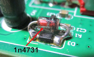
Without the LEDs: The logic voltage is controlled by a zener diode tagged D3 on the board. To adjust this to safe voltages you can simply bridge a 1N4731 (4.3 volt) zener diode across it.
After adding the diode, check the voltages on the switch again and you should see about 3 volts with the switch on.
If you are not adding the extra indicators, this fix is adequate.
With the Clipping and Protection LEDs:
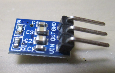 If you are adding the extra indicators, you will need to use one of these tiny 3.3 volt regulator boards, pictured on the right. These are available from
Amazon
as well as many other outlets. They use the AMS1117-3.3 regulator chips which can provide 3.3 volts with more than enough current for the amplifier and the monitor panel.
If you are adding the extra indicators, you will need to use one of these tiny 3.3 volt regulator boards, pictured on the right. These are available from
Amazon
as well as many other outlets. They use the AMS1117-3.3 regulator chips which can provide 3.3 volts with more than enough current for the amplifier and the monitor panel.
It is mostly dumb luck, but with a simple modification the pins on these tiny boards will line up with the connections we need from the Fosi board so that you can surface solder the regulator board in place without too much trouble.
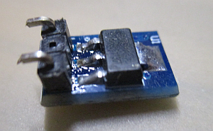
- Prepare the regulator board. by unsoldering the pin header, removing the middle pin, then re-soldering it to the opposite side of the board and trimming the bent part of the two remaining pins to about 2mm in length.
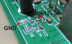
- Test the regulator by applying +12 volts on VIN and GND pins and test the centre pad for +3.3 volts.
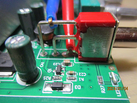
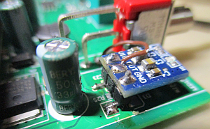
- Next remove Q1, R1, R25 and D3 from the amplifier board.
- Remove the solder resist from the centre lead of Q1 to expose copper up to the top of the "Q".
- Solder a length of wrapping wire to the bottom leg of the power switch.
- Clean the centre pad of Q1 and the cathode side of D3 and add fresh solder.
- Tin the bent part of the leads on the modified regulator board.
- Position the regulator board so that the VIN pin sits exactly on the centre pad for Q1 and GND sits on the cathode pad for D3, being careful to avoid the remaining two solder pads from the transistor.
- Heat the regulator pins to attach it to the main board by solder re-flow.
- Finally attach the length of wire from the switch to the VOUT pad of the regulator.
If all went well, you can now connect the power brick to the amplifier board and you will see the led on the regulator board glowing. Checking the switch, you should have a stable 3.3 volts across the top and bottom legs.
Summary:
The final test, no matter which method you chose, is to connect the amplifier board to power, speakers and a source. Play some music while turning the amplifier on and off. If the power switch is reliable, this step is completed.
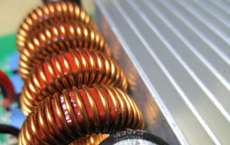
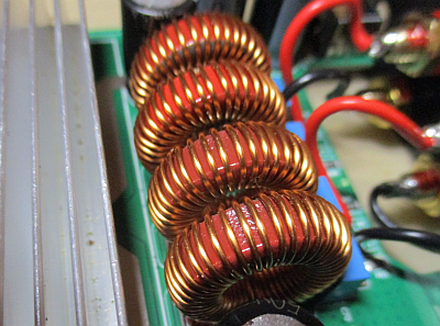
Coils vs. heatsink Home Top Chapters
This fix applies to all versions of the TB10D board, to date. (ver2.2)The key to success in a Class-D amplifier is its output filter. These need to be designed with abundant care if the amplifier is to sound good and last a long time. The TB10D has very nice filters, using robust toroid coils and high quality capacitors that don't saturate until the edge of clipping on 4 ohm loads. Unfortunately Fosi's designers chose to butt them right up against the back of the heat sink, pretty much undoing their merits.
Theory tells us there is no magnetic field around a toroidal inductor. But that's not entirely true. Leakage happens. There is a circumfrential field caused by force lines on the outside of the windings that, while not strong, can still cause problems if the coil is not operating in free space. This extra magnetic force is attenuated, and short ranged, but it is still there.
This YouTube Video explains it better than I can.
Theory also tells us that when magnetic lines of force intersect a conductive material of sufficient mass --like a heatsink-- there will be eddy currents induced into the mass. Then, since the electrical resistance of the heat sink is almost zero, those eddy currents can be quite strong, causing both inductive heating of the heatsink and cross-coupling between multiple coils.
The output coils on a TPA3255 chip are handling up to a 48 volt chain of square waves at 400+ khz, as well as the current from the audio information. Even at reduced output levels warming of the heatsink and unbalancing of the output filters can be quite noticeable.
So: Keep the big blob of shiny metal away from the curly wire thingies.
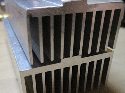
Fortunately there's a very simple solution: Cut one fin off the heatsink to open a gap between it and the output coils.
- Undo the two bolts on the bottom of the board and remove the heatsink.
- Slip a hacksaw between one of the outside fins and the second fin and cut the base of the heatsink even with the base of the second fin.
- Clean up your cut with a file and remove any uneven or sharp edges.
- Clean away the old thermal compound from both the chip and the heatsink using isopropyl alcohol.
- Put a thin layer of fresh thermal compound on the chip top. (More is not better)
- Reinstall the heatsink, short side toward the coils, remembering to put the spacers back on top of the board.
- Tighten snugly.
To test this hook the amplifier up to power, source and speakers and listen to it for a while at moderate volume levels. Then check the heatsink to see if it is getting overly hot.
Summary:
Contrary to the arguments about reduced cooling after cutting the heatsink, the amplifier actually runs cooler since there is no magnetic heating going on. When idling, the casing sits at room temperature and when playing at conversational levels, it gets only moderately warm to touch.
There is also a noticeable improvement in sound quality. The first impression is that the output seems easier, more relaxed. The overall impression is one of bass that is clear and unencumbered, with good clear mids and highs. Testing also confirms a reduction in distortion and less crosstalk between the two channels. How audible this might be will depend on your system, room and other factors.
Fancy blinking lights Home Top Chapters
Please note: This section is optional. But if you are going to add the LED panel, you will need to first install the AMS1117-3.3 voltage regulator per the instructions above.Professional amplifiers have long featured indicators for when things where getting out of hand. These most often include a "Clipping" lamp that will blink when the amplifier is overdriven and a second "Protect" lamp to indicate the amplifier has gone into it's self-protection mode.
The TPA3255, having it's genesis in pro-audio, supports these features on two of it's output pins. Pin 19 is ~FAULT which latches low to indicate the chip has shut down and needs to be reset to continue. Pin 21 is its ~CLIP/OTW signal where it indicates overdrives by pulsing the pin low and over-temperature warnings by latching the pin low. The full operational details of these pins are in the TPA3255 Data Sheet, starting on page 17.
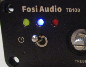
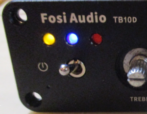
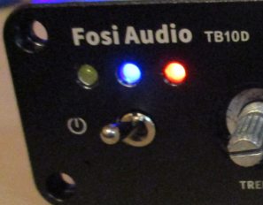
Where and how you position your LEDs is entirely up to you. I put them above the power switch because that's what made sense to me. I considered centring them in the blank spot to the right of the Fosi Audio logo, above the tone controls, beside the power switch, etc. and every time I ended up thinking they would look best above the power switch. You might decide to put them in a different spot or space them differently and that's entirely up to you.
On most pro-audio amplifiers the power light is blue, the clipping light is yellow and the protection light is red. But this is a custom, not a rule. I finally decided to change the order putting the blue LED in the middle, directly above the power switch, for aesthetic reasons.
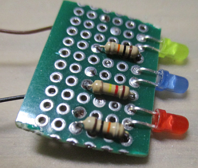
No matter where you place the LEDs or how you space them, you will need to make a small perfboard circuit to support and align them with your drill holes in the faceplate. The schematic is simplicity itself. Three LEDs and three 1/8 watt resistors. The board is more for mechanical support than anything else.
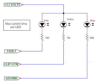
The best place to get 3.3 volts is from the middle (switched) leg of the power switch.
You can take the ground connection from the back leg of the power switch.
However; the ~CLIP/OTW and ~FAULT signals must be obtained directly from the TPA3255 chip itself.
So, ladies and gentlemen, please allow me to introduce you to the soldering job from hell...
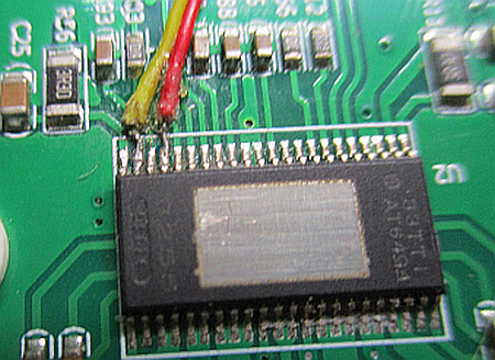
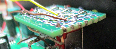
The task is to attach 30ga wrapping wire directly to two of the TPA3255's pins, as shown. Cut the wires extra long so you have plenty to reach your LED board. The yellow wire on pin 21 carries the ~CLIP/OTW signal and the red wire on pin 19 handles the ~FAULT signal.
These pins are very small. This is a job for a good iron, with a very fine tip. The best bet is to apply some flux, pre-tin the wires and make the connection by solder re-flow. I used a bit of stickum to help position the wires before soldering. With a gentle, steady hand and a good magnifying glass, it's not really all that hard... just tedious.
Be very careful after making these connections. Before powering the board, you must test for shorts with adjacent pins using extra fine probes on your multimeter. Also check your added wires for continuity at the chip. I also used the point of a sewing needle to gently clean between the pins, making sure there is a bit of clearance. Finally, make sure none of this stands above the top of the chip, where it might contact the heatsink.
If all tests well, use a couple of tiny spots of crazy glue to fasten the wires in place at the chip and again at the edge of the heat sink. You don't have a lot of room, so make sure they lay flat on the circuit board.
Let the glue dry and then you can reinstall the heatsink with fresh thermal compound and connect the two wires from the chip to your LED board.
Now you will need to prepare and drill the faceplate. Keep in mind that in order to open the amplifier and work on it, you have to remove the faceplate, so you will need some means to either dismount the LEDs or have them stay with the amplifier board, should you need to get inside.
In my case I elected to have the LED board stay with the amplifier board when the case is opened. I did this using a small U shaped piece of stiff wire. I lined the LEDs up in the drill holes and then soldered the wire support to the top lead on the power switch (which is grounded). It doesn't have to be especially strong, it only has to prevent the LEDs from backing out of the holes and support the board when the front cover is removed.
The testing step is to hook the amplifier up to a power supply and signal generator and make sure the LEDs are actually working. First, just turn it on and see the blue power LED, then feed the amp a signal and drive it into clipping to see the yellow LED then, finally, turn the power supply down to force it into under-voltage protection to see the red LED. If all this works, you're good to go.
Now that you have the LED panel working, if you find the LEDs on the voltage regulator and/or the main amplifier board to be unnecessary or annoying, you can feel free to remove them.
Finally, reassemble the amplifier into it's casing.
Summary:
Soldering all this up was a real challenge. The two wires on the chip itself were the hardest soldering job I've ever done and it's a joy to see it work.
Summing up Home Top Chapters
There is little doubt the amplifier is improved.Fixing the logic supply was the most important job, since it was being run over-voltage and would have eventually caused the chip to fail.
Getting the heatsink away from the coils definitely improved the amplifier's performance. It runs cooler, distortion is now below the threshold of my test gear, and there is less crosstalk between channels. So that's all good.
Adding the Clip and Protect warning LEDs was a real challenge. But, in the end, I think it was well worth doing since I can now see when I'm pushing things too hard.
Wait... What? There was a warrantee?
Oh well.