 Contact
Home
Chapters
Contact
Home
Chapters
A07 Upgrade
The Mini-Amp revolution began with Class-T (Tripath) based amplifiers that sat on your desk to power computer sound or play CDs through smaller bookshelf speakers. The original designs worked on 12 volts and offered about 10 clean watts per channel. More than enough for a compact desktop system.
It wasn't long before other companies got into the game and began producing Class-D amplifier chips. The Texas Instruments TPA3116 and ST Microelectronic's TDA7492 were popular and offered more power and better sound than the original mini-amps. These little guys could get up to about 35 watts per channel and could drive efficient floor standing and bookshelf speakers to reasonable volumes.
Then, in 2016, Texas Instruments offered the TPA3255 chip which was a quantum leap forward in Class-D technology. Now, this chip is ubiquitous in the Mini-Amp market becoming the basis for more and more capable amplifiers in surprisingly small cabinets and at prices that are hard to ignore.
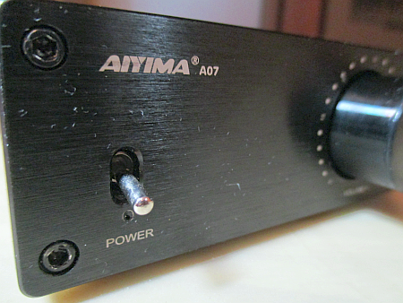
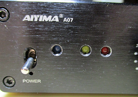
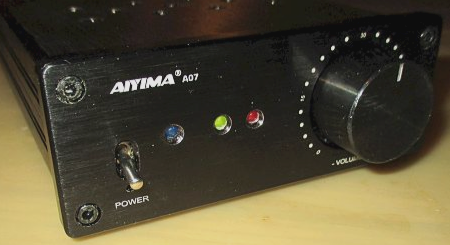
In 2020, Aiyima introduced the A07, with it's promise of well over 100 clean watts per channel, able to power almost any speaker to very loud levels. This mini-amp was the game changer. The A07 is still in production and is routinely upgraded by Aiyima. It is the little amp that could.
About Class-D Home Top Chapters
There is a common misunderstanding that Class-D means "Digital". It does not. The "D" designation was simply the next letter in the alphabet after A, AB, B and C. Everything a Class-D amplifier does happens in the analogue domain.Unlike it's predecessor technologies, Class-D does not use brute strength to deliver it's output. Instead it uses a modulation technology known as Pulse Width Modulation or PWM, for short. In this scheme an audio signal is used to Modulate the ratio of on-time to off-time in a high frequency chain of square waves. After that, all you need to do to get the amplified audio back is filter out the square waves using a coil and capacitor low pass filter. It's simple and when done right it is very effective and surprisingly efficient.
The following is advanced level DIY modification. You will need to be skilled with soldering, hand tools, a drill and test equipment to successfully complete all these tasks.
Bulk supply Home Top Chapters
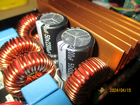
The A07 is an "always on" device. So long as the power brick is plugged in and working, the power supplies in the amplifier are energized. This has the advantage of keeping the amplifier ready to go without risking the repeated current inrush that can kill a power brick while charging the internal capacitors.The only bulk power related change I made was to replace the two large bulk capacitors located behind the heat sink. I removed the 1200uf caps and installed 2200uf 50 volt caps in their place. This provides more burst power for transients and sustain for deep bass. This change is audible when listening at reasonable levels.
Note that when changing these big caps, their height matters. The new ones cannot be any taller than the factory parts. There is very little clearance inside the case and if your caps are taller they may touch the top of the casing, causing some very exciting results. So, when re-assembling the case, before installing the front plate, I suggest you place a strip of paper on top of the caps and then pull it out the front to ensure at least minimal clearance. If the paper is trapped by the top cover, you may run into problems.
Regulated supply Home Top Chapters
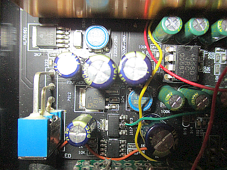
Aiyima has done a credible job designing the internal power supplies for the A07. Like the bulk supply, the regulated supplies are always on and ready.The pre-amp power is derived from the bulk voltage by an XL7015E1 buck converter, providing 15 volts of regulated DC power. Following this, they have used a linear 7812 regulator to further smooth and regulate the 12 volt Op-Amp supplies which are very clean and ripple free. The final step is a 1117-3.3 regulator for the logic voltages. This too is noise and ripple free, so I elected to leave this section as is from the factory.
Volume control Home Top Chapters
The original A07 design used a 50k linear volume control. I was all set to replace it with a 10k audio tapered pot, but Aiyima beat me to it. The latest board version (231106) came with an Alps A10k pot installed.This both provides a smoother experience when adjusting volume and eliminates the "mid-rotation sag" in the bass when the upper and lower halves of the pot are effectively in parallel producing a series resistance of 12.5k ohms. With the new volume control, it's now about 2.5k and the tonal shift is no longer audible.
If you have an older version, changing the volume control is not especially difficult. It's mostly a matter of unsoldering the small bridge board it sits on, unsoldering the old pot and installing a new one, then reattaching the bridge board.
Preamplifier Home Top Chapters
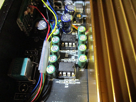
The pre-amplifier section of the A07 consists of 2 dual op-amps in 8 pin sockets. These chips are primarily phase splitters feeding the balanced inputs of the TPA3255 chip. But they also provide about 6db of gain (2x voltage gain) that is a big help to older source devices like turntables or tuners that have 0.7 volt outputs and would not be able to drive the amplifier to it's full output.The standard chips are NE5532 dual low noise op-amps. Unfortunately these are one of the most frequently counterfeited chips. It is not uncommon to find re-branded "something else" chips when doing service or examination work. So, I've taken to just replacing them with RC4558 chips wherever I find them. There is no appreciable difference in performance or sound between the real 5532 chip and the 4558 chip, so the goal in changing them is to ensure the amplifier is not going to fail because of a fake chip.
Some Audiophiles like to tinker with "chip flipping" in these little amplifiers. They will often spend more money on "high end" replacement chips than on the amplifier itself. While I seriously doubt the value of this activity for improving sound quality, it is very hard to deny the wear and tear on the two sockets.
The sockets themselves are of reasonable quality. But no dual inline socket is designed for more than a few chip changes. Generally they are used to allow easy service on parts that tend to fail. They're not intended to be cycled more than 2 or 3 times in the life of their host device and at some point they will fail. Replacing them is a costly and labour intensive job. So I will advise keeping the chip flipping to a minimum.
When changing chips, the best method is to get a firm grip on the two ends of the chip with a chip extracting tool and rock the chips gently end to end, walking them up out of the socket in small steps. When inserting the replacement chip, you should use a magnifying glass and check that all 8 pins are started into the holes before pressing the chip into place.
Output stage Home Top Chapters
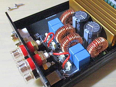
The heart and soul of a Class-D amplifier is it's output filters, where the amplified audio is recovered. Aiyima has done a credible job with these filters. The coils are robust, using heavy gauge wire. They are spaced well apart and a respectful distance from the heat sink. The filter capacitors are high quality and arranged nicely.The output connectors are binding posts. You can use banana plugs, spades, or raw wire. They are of the shallow type, typical of these amplifiers, but they are well made and they do make an adequate connection to your speaker leads.
In testing I saw no signs of DC offsets, saturation or overheating. Thus, no reason to tamper with this.
Case ventilation Home Top Chapters
These little amplifiers can run very hot especially with the 48 volt power supplies. This is because the case is fully enclosed with no air circulation at all. A heat sink in a closed space becomes a heater. So, we do need to do something about that.There are quite a few variations in cooling solutions for the A07. If you do some online searching you will find plenty of good ideas and (unfortunately) a few bad ones. So, give this some thought and choose your solution carefully.
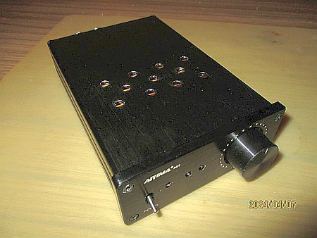
I didn't want noisy fans or ugly wire cages. For me, it needed to look like something that could have come from the factory. So, after some head scratching I finally chose a 4-3-4 grid of holes above the heat sink in the top of the case, with 3 extra holes in the bottom to allow cool air in.
Nicely, this is also a pattern of holes that is easy to make with a hand drill. Begin by fully disassembling the A07's case and setting the front panel and PCB aside. You only need to mark and drill the top and bottom shells.
Note that the A07's top and bottom shells only fit together one way. One side has a tongue, the other has a groove. You should mark front and back of each piece to be sure you orient the top and bottom holes correctly.
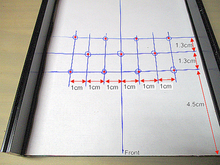
The layout sheet for the top is shown on the right.
- Cut a sheet of paper that just fits inside the A07's top cover.
- Now draw a centred line along the length of the sheet.
- Using the dimensions in the image, mark up your drill points.
- After checking the alignment of the grid with the heat sink, tape the paper sheet down inside the top case half being careful to orient it to the front.
- Using a spring loaded centre punch, mark all the dotted intersections.
- Remove the paper sheet.
- Using a small bit, drill pilot holes at every punch mark.
- Increase your bit size and drill until you have 5mm holes in each spot.
- Using a countersink, chamfer and de-burr your holes.
- Finally apply a thin coat of black nail polish to the raw aluminium you've exposed.
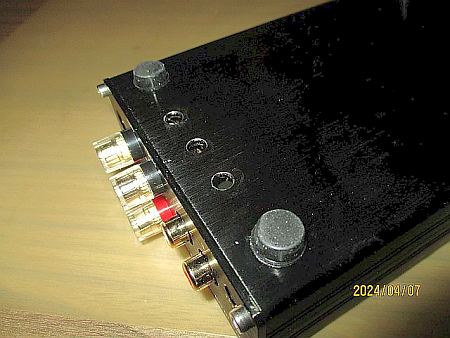
The bottom is easier.
- Put some masking tape along the back edge of the bottom case.
- Measure in 1.5cm from the back edge and draw a line.
- Measure to the centre of the case and mark the intersection.
- Measure 1.5cm from each side of centre and mark the intersections.
- Centre punch and drill.
- Chamfer and de-burr the holes.
- Paint the exposed aluminium with black nail polish.
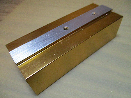
Heat sink Home Top Chapters
My one remaining concern about cooling enhancement was that the gold coloured heat sink is not likely as efficient as a raw aluminium one would be. I contacted Aiyima and they have confirmed my suspicion. So, if you can find a raw aluminium heat sink that fits, I recommend swapping it in when doing this upgrade.At the very least, you should consider removing the gold coloured plating from the raised bottom area that contacts the TPA3255 chip.
- Disassemble the amplifier and remove the heat sink.
- Clean away the old heat sink compound.
- Get some medium-fine sandpaper and tape a sheet down on your work table, grit side up.
- Now rub the raised bottom part of the heatsink lengthwise, back and forth, on the sandpaper until you have fully exposed the raw aluminium.
- Carefully clean away any loose particles.
- Apply a thin layer of new thermal compound on the chip.
- Reassemble.
Warning lamps Home Top Chapters
Pro-audio and many vintage amplifiers have a system of lamps to warn the end user of overloads and protection triggers. For some reason this has largely vanished from modern amplifiers and has never been implemented with the current batch of mini-amplifiers. This, despite producing enough power to damage many speakers.
Thanks to it's roots in pro-audio, the TPA3255 has native support for the two most common warnings: Clipping and Protection.
The first of these is the FAULT signal which originates on pin 19 of the chip. This is an open drain signal that latches low when protection is activated.
The second is the CLIP/OTW signal on pin 21. This is also an open drain, active low signal. It will pulse low when the amplifier approaches clipping (overdrive) levels and it will latch low if the chip becomes too hot.
Optionally, if you want a nice blue pilot light it is a fairly simple task to replace the red one from the factory with one of your own making.
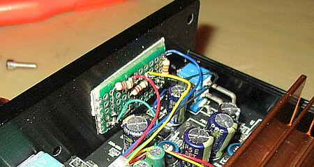
The circuitry for these features is not complex. Each requires only an LED and a 1/8 watt current limiting resistor to work. I generally build a small perfboard with the LEDs soldered through from one side and the resistors surface mounted on the back side. I then drill the front panel to match the LEDs and affix the whole thing to the front panel with double sided carpet tape. (But leave the drilling part until the last step.)
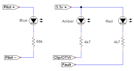
You have considerable flexibility in how you arrange your warning lights. I chose the layout shown above, because it's easy to build. But you could (for example) build your own board to position the blue pilot light above the power switch and have the clipping and protection LEDs vertically beside it. This is up to you. Of course, this will change the way you build the perfboard. Give the layout some thought first; once you drill the face plate there's no turning back.
For safety, you should build and test your perfboard using an external 3.3v power supply. You can vary the brightness of each LED by adjusting the value of the series resistors. Be aware that you must not exceed 5ma of current for each of the LEDs or you risk damaging the TPA3255 chip. The final values will depend on the LEDs you are using and your own preferences in brightness. The values shown give a soft blue pilot light with brighter clipping and protection lamps.
Now comes the complication:
These signals are not implemented in the A07. While the TPA3255 chip supports them the amplifier does not. To access them you will need to attach lengths of 32ga wrapping wire directly to pins 19 (Fault) and 21 (Clip/OTW) of the chip itself.
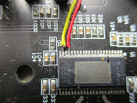
If removing the heat sink and seeing how painfully small those pins are does not dissuade you, you will need to work through a magnifier with a very fine tip on your soldering iron. The best method is to:
- Cut generous lengths of wire
- Strip only a tiny bit at the chip end
- Pre-tin the exposed wire ends.
- Position the wires on top of the pins one at a time
- Make the connection by solder re-flow.
Once you have the two wires attached, you will need to check very carefully for pin-to-pin shorts and also ensure you have good continuity between the pins and the far end of the wires. You will also have to be careful the wires do not stand above the top of the chip, to prevent them from touching the heat sink.
Once you are sure your connections are clean and good, use a small drop of crazy glue to attach the wires to the circuit board, route them out towards the front of the board, making sure they are laying flat and add a second small drop where the edge of the heat sink will be.
Now that you have your two warning signals out where you can get at them, apply a thin coat of thermal grease to the chip and re-attach the heat sink.
Leaving enough extra wire to allow removing the face plate, attach your leads to the appropriate perfboard mounted resistors.
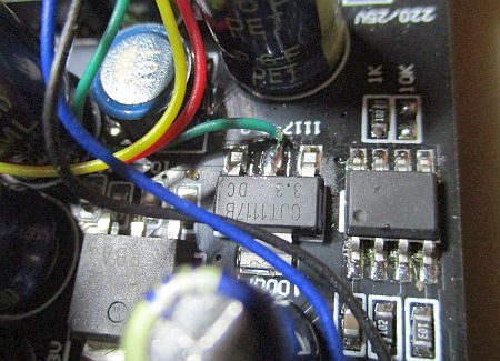
Your best place to get 3.3 volts to drive the LEDs is the middle pin of the 1117-3.3 regulator chip:
- Locate the 3.3v regulator on the board.
- Pre-tin the ends of some wrapping wire.
- Position one end on the regulator's centre pin.
- Make your connection by solder re-flow.
- Attach the other end to the common anodes of the two LEDs on your perfboard.
Next you will want to test your work.
- Hook the A07 up to a variable power supply, a signal generator and 8 ohm dummy loads.(using speakers will make a LOT of noise).
- Adjust the power supply to about 24 volts
- Power up the amplifier. (It should turn on like normal.)
- Turn the amplifier's volume control all the way up.
- Feed in a test tone.
- Increase the tone level until the Amber clipping light comes on.
- Turn the power supply voltage down to about 15 volts.
- You should see the Red protection light come on and the Amber clipping light go out.
Compared to what you just accomplished, the blue pilot light is easy.
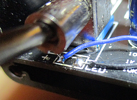
- Power everything down.
- Remove the red LED from under the power switch.
- Clean the two solder pads.
- Add a little bit of fresh solder.
- Attach two lengths of wrapping wire to the LED's solder pads.
- Attach the other ends to the Blue LED circuit on your perfboard.
The test for the pilot light is simple:
- Power the amplifier with about 24 volts.
- Turn the front panel switch on.
- The Blue power LED should glow after about 2 seconds.
- Turn the front panel switch off.
- You should see the blue LED go dark.
So now that it's built and tested, it is time to drill and chamfer the faceplate, reassemble the amplifier, mount your perfboard and tidy up the wiring.
Finally, put the top cover on and... all done.
Summing up Home Top Chapters
In my opinion the Aiyima A07 is still one of the best of the TPA3255 mini-amps. The design and engineering is very good as is the sound quality.We've seen a couple of minor improvements in lower bass because of the larger bulk capacitors and the new volume control but nothing big or surprising.
The big gains with this upgrade are in case ventilation and enhanced cooling. The amplifier now idles at room temperature and gets only modestly warm in normal use. Blasting loud music will get it warmer, but never hot like it used to.
If you've added the warning lights, you now have a nice Amber LED that flickers on to tell you "you're getting carried away" and a Red one that says "I told you so!" to help you keep your listening sessions within the capabilities of the chip.
As a final note: I will urge companies who are designing with the TPA3255 to always implement the warning lights. They're a simple addition and a lot of tweeters will thank them.
Another warranty down the drain, but it's worth it.
Happy Listening!